Most people agree that our technology is getting smarter, but most don’t realise just how smart! In reality, smart technology is around us every day and is developing faster than we can keep up. Today’s smart technology is watching us, helping us, and is getting smarter because of us.
The New and Innovative KT Commander Series Smart-Touch Switch Panel is another KT innovation, helping us move forward with the times. If you are an Electrician or simply a DIY handyman, You may be familiar with the ‘Switch Panel’ or Switch Bank’ which typically looks like a row of rocker switches mounted into one housing to form a ‘panel’. The switches rock backwards and forwards, ‘On and Off’ to provide power to appliances. This basic technology has carried us through until now . . .

KT have designed and developed it’s very own Innovative ‘KT Commander Series Smart-Touch Switch Panel’ which functions using heat-sensitive touch technology, just like your ‘Smart Phone’. Simply by touching the ‘Smart-Touch Screen, you have the ability to power lighting and other 12V appliances in Caravans, Motorhomes, Vehicles, Heavy Machinery, Boats and more. There are a wide range of applications as the KT Commander Series Smart-Touch Switch Panel can be used for ‘ANYTHING’ 12V. A sleek design allows it to be mounted almost flush with a surface, giving it a clean and tidy finish.

Available in 4 way (single voltage) and 8 way (dual voltage for dual battery systems), the KT Commander Series Smart-Touch Switch Panels provide 20 Amps per circuit which goes above and beyond current switch panels on the market. Each pack also includes 48 programmable icons that are easily changed to suit the application of each circuit.


A backlit LED screen allows for easy ‘ON/OFF’ identification. Switch Panel Buttons illuminate to BLUE indicate when a circuit is active ‘ON’ and powering a device.
When circuits are inactive or switched ‘Off’ the LED’s will default to AMBER. The LCD Voltage display assists in determining how much power appliances are drawing from the battery and can be checked at any time
FEATURES:
- Basic D.I.Y Wiring & Installation
- 4 Way Switch Panel, 20 Amps per circuit (80 Amps total)
- 8 Way Switch Panel, 20 Amps per circuit ( 160 Amps total)
- Single & Dual LCD Voltage Display
- Green ‘On’ and default Amber ‘Off’ Backlit Touch Screen for easy On/Off identification
- Over 48 icons to suit a wide range of applications
- Suitable for automotive and marine applications
- 12 Months Warranty on manufacture & build

MOUNTING:
- Prepare the area to mount the switch panel. Use the mounting guides supplied in the manual included with your switch panel. This template will allow you to accurately measure and drill holes. Mounting guides provided are scaled to the exact size of your KT Commander Smart-Touch Switch Panel.
- Once your area has been prepared, drill the mounting holes to suit the self tapping screws included with your KT Commander Smart-Touch Switch Panel.

INSTALLATION:
- When installing 4 Way (Single Voltage Display) KT Commander Smart-Touch Switch Panel, ensure to run the GROUND ( – ) wire to the battery and the Positive ( + ) to the battery. When installing the 8 Way (Dual Voltage Display) KT Commander Smart-Touch Switch Panel, ensure to run the GROUND ( – ) wire to the battery and the Positive ( + ) to Battery A and the other Positive ( + ) to Battery B.
- When connecting 12 devices, follow the circuit diagram on pages 1 and 2 for easy identification of each switch and the relating terminal/circuits to connect your Positive ( + ) wire.
-
IMPORTANT: It is recommended to use an ON/OFF Isolation Switch with your KT Commander Switch Panel to turn OFF your panel when not in use. Failure to install an isolation switch may result in the switch panel draining your battery as the switch panel is ‘Live’ once the GROUND (-) wire is connected.
For 4 Way KT Commander Smart-Touch Switch Panels: Once you have connected GROUND ( – ) wire and Positive ( + ) wire to the battery, your switch is now live and will immediately provide your batteries voltage reading.
For 8 Way KT Commander Smart-Touch Switch Panels: Once you have connected GROUND ( – ) wire and one Positive ( + ) wire to battery A and one Positive ( + ) wire to battery B, your switch is now live and will immediately provide a voltage reading for battery A and battery B.
- When connecting to a 12V device, e.g.; a work light, connect the positive wire to one of the switches of choice. Providing the device has been grounded through the Negative Wire, your device should now be live.
- Select the icons of your choice which best indicate the application of your device. The below comprehensive range of icons are included with your KT 4 and 8 Way Commander Smart- Touch Switch Panel. Ensure to remove the black frame and glass before applying your icons onto the clear recess covering the switch panel touch buttons. Icons can be easily removed and replaced to change the use of the switch.

 PROTECTION – FOR ALL APPLICATIONS, CARAVAN, MARINE & AUTOMOTIVE
It is highly recommended to use a fuse holder within the circuit, between your device and the switch panel for protection. An ON/OFF Isolation switch should also be installed in conjunction with your switch panel to turn OFF the panel when not in use to avoid draining battery. Your switch panel is LIVE after connecting the GROUND (-) wire.
Should this recommendation not be followed, your device is at risk of damage should an electrical fault be present. Ensure to follow these instructions to avoid voiding warranty. AECAA Pty Ltd will not be responsible or liable for any damages caused by failure to follow these instructions. (See page 6 of the manual for more warranty information).
IMPORTANT:
The KT Commander Smart-Touch Switch Panels are splash-proof when mounted correctly and can be used for a variety of applications including Caravans, Motorhomes, Vehicles, Heavy Machinery, Boats and more.
Should you be using your KT Commander Smart-Touch Switch Panel for marine applications including on boats or yachts, it is recommended to mount your switch panel in a location where the panel wont be directly exposed to water. Exposing your KT Commander Smart-Touch Switch Panel to water may result in damage to either your panel, your circuits or your connected devices and all warranties will be void.
It is highly recommended to use a fuse holder within the circuit, between your device and the switch panel for protection. Should this recommendation not be followed, your device is at risk of damage should an electrical fault be present. Ensure to follow these instructions to avoid voiding warranty
OPERATION INSTRUCTIONS:
The KT 4 & 8 Way Commander Smart-Touch Switch Panel is a simple and efficient way to control your devices from one location.
The KT Commander Smart-Touch Switch Panel buttons will illuminate BLUE to indicate that a circuit/device is turned ‘ON’ and ACTIVE.
2. The KT Commander Smart-Touch Switch Panel buttons will illuminate AMBER to indicate when a circuit/device is turned ‘OFF’ and INACTIVE.
3. When a circuit is turned ‘ON or ‘OFF’, The KT Commander Smart-Touch Switch Panel will make a ‘click’ sound.
The Single Voltage Display for the KT 4 Way Commander Smart-Touch Switch Panel and the Dual Voltage Display for the KT 8 Way Commander Smart-Touch Switch Panel will immediately provide the battery/batteries voltage. The voltage will drop once devices are turned ‘On’.
Ensure to turn ‘OFF’ your switch panel when not in use via the ON/OFF isolation switch which should be installed along with your panel to prevent draining of battery.
SAFETY:
The KT Commander Smart-Touch Switch Panels are splash-proof when mounted correctly and can be used for a variety of applications including Caravans, Motorhomes, Vehicles, Heavy Machinery, Boats and more.
Should you be using your KT Commander Smart-Touch Switch Panel for marine applications including on boats or yachts, it is highly recommended to mount your switch panel in a location where it will not be exposed to direct sunlight, water or rain. Failure to follow these instructions may result in water damage to either your panel, your circuits or your connected devices and all manufacturing warranties will be void. The KT Commander Smart-Touch Switch Panels are manufactured using U.V resistant materials, however mounting your Switch Panel in a location where it may be exposed to direct sunlight is not recommended.
CLEANING:
The best way to clean your KT Commander Smart-Touch Switch Panel is by using a microfibre cloth. To clean dirt or dust from underneath the glass touch panel, use a gentle detailing brush. To clean finger prints off the external glass touch surface, use a lightly dampened microfibre cloth.
IMPORTANT:
Do not apply any cleaning products to your KT Commander Smart-Touch Switch Panel.
SPECIFICATIONS:
For more information on the KT Commander Series Smart-Touch Switch Panels or to find a stockist, please contact us through the below contact form.


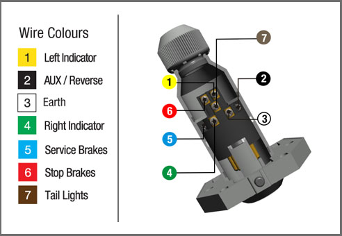
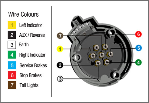
 Wiring up a 7 Pin Trailer Plug or Socket